The availability factor of wind and solar power plants depends on whether periods when the plant is operational, but there is no wind or sunlight, are counted as available, unavailable or disregarded. If they are counted as available during these times, photovoltaic plants have an availability factor approaching or equal to 100%. Modern wind turbines also have very high availability factors, about 98%. However, solar and wind plants have relatively low capacity factors. Wind capacity factors range from 20-40% and solar capacity factors in Arizona are about 19%. This makes wind and solar availability factors much lower if times when sunlight or wind are not available are taken into account.
Wind Energy Availability
The power that is available in the wind depends on the wind speed, the density of the wind (which varies with altitude and temperature), and the amount of turbulence (swirling) in the wind. Wind speed is high up in the sky and low at the ground level. You may notice that you are difficult to fly a kite at the ground. However, when the kite is flied up in the sky, you will feel the high wind force.
The power available at a given wind speed passing through an area (e.g. a window) can be calculated by using the following formula
P = ½·ρ· A·v³
Where:
- P is power in Watt (W).
- ρ is the density of air in Kilograms per cubic meter (Kg/m3)..
- A is the cross section area of the wind passing through in sq. meter (m2).
- v is the velocity of the wind in meters per second (m/s).
The density of air at sea level and room temperature is approximately 1.3 Kg/m3. The available power from the wind increases dramatically with the swept area but so do the stresses on the blades. The swept area is the area the windmill’s blades cover during a rotation.
The power depends on the cube of the velocity. This means that when the wind speed doubles, the available power is increased by a factor of 8. In other words, when the wind speed reduces in half, the available power reduced to 1/8 of the original value. There is very little available power below 11 Km/h, but as wind speed increases the power becomes very significant.
Turbulence and Drag are always associated with wind. They cause rapid variation of pressure and velocity in space and time. They detract our ability to extract mechanical energy from the wind. In general, wind turbines are typically installed as far above ground level obstacles as possible, since trees and buildings add to turbulence.
Beaufort scale – The Beaufort scale is an empirical measure that relates wind speed to observed conditions at sea or on land. Its full name is the Beaufort wind force scale, although it is a measure of wind speed and not of force in the scientific sense.
Wind Shear – In many assessments of the wind potential the upper anemometers of the wind measurement are installed at a height of 40 m above ground while the hub height of modern wind turbines today often reaches heights between 55 m and 60 m above ground level. To estimate the wind regime at hub height of the wind turbines (the WAsP model simplifies the wind speed distribution over the rotor as concentrated to the hub height) the wind speed is extrapolated according to the following formula:
Whereas γ is the Power Law Exponent or Wind Gradient which is depending on the roughness of the terrain, the thermical lamination of the atmosphere, the wind speed itself and the height above ground. The exponent must be calculated sectorwise for the wind park site. This can be done by the WindPro-Software package from the measured wind data at the heights of 10 m a.g.l. respectively 40 m a.g.l..
The wind gradients for the twelve wind distribution sectors describe the wind speed at different heights for all wind directions divided in sectors of 30°.
Wind Speed – Wind speed data are the most important indicator of a site’s wind energy resource. Multiple measurement heights are encouraged for determining a site’s wind shear characteristics, conducting turbine performance simulations at several turbine hub heights, and for backup.
Wind Direction – To define the prevailing wind direction(s), wind vanes should be installed at all significant monitoring levels. Wind direction frequency information is important for identifying preferred terrain shapes and orientations and for optimizing the layout of wind turbines within a wind farm.
Temperature – Air temperature is an important descriptor of a wind farm’s operating environment and is normally measured either near ground level (2 to 3 m), or near hub height. In most locations the average near ground level air temperature will be within 1 ° C of the average at hub height. It is also used to calculate air density, a variable required to estimate the wind power density and a wind turbine’s power output.
Estimation of Wind Energy Potential
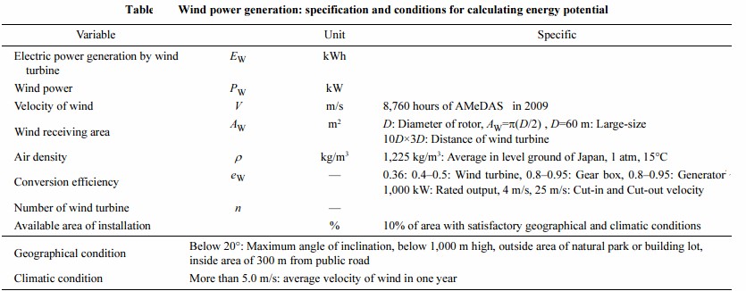
Wind power depends on the wind receiving area, air density and kinetic energy. Kinetic energy can be estimated from the mass and velocity of air. The wind energy potential can be expressed as

where PWT is the total power received from the wind turbines, ρis the air density, AW is the wind receiving area, V is the velocity of air, and ew is the conversion efficiency.
In this equation, 10–3 means to change the unit from k to kW. Therefore, the total wind energy potential (Ew) can be expressed as

where V is the function of time t, and n is the number of wind turbines. The parameters for the estimation of energy potential from wind are listed in the table. The specific conditions based on geography and climate for each of the parameters have been defined in detail. Wind turbines (1,000-kW-rated output) were installed in the selected geographical locations based on slope, height, and surroundings. The land slope for the turbines should usually not exceed more than 20°, and installations should not be placed at more than a 1,000-m height from ground level. Wind turbines must be installed outside the areas of natural parks and buildings.

Basic Sensors
Meteorological sensors are designed to monitor specific environmental parameters.
Wind Speed – Cup or propeller anemometers are the sensor types most commonly used for the measurement of near-horizontal wind speed.
- Cup anemometer: This instrument consists of a cup assembly (three or four cups) centrally connected to a vertical shaft for rotation. At least one cup always faces the oncoming wind. The aerodynamic shape of the cups converts wind pressure force to rotational torque. The cup rotation is nearly linearly proportional to the wind speed over a specified range. A transducer in the anemometer converts this rotational movement into an electrical signal, which is sent through a wire to a data logger. The data logger then uses known multiplier (or slope) and offset (or intercept) constants to calculate the actual wind speed.
- Propeller anemometer: This instrument consists of a propeller (or prop) mounted on a horizontal shaft that is oriented into the wind through the use of a tail vane. The propeller anemometer also generates an electrical signal proportional to wind speed.
Wind Direction – A wind vane is used to measure wind direction. The most familiar type uses a fin connected to a vertical shaft. The vane constantly seeks a position of force equilibrium by aligning itself into the wind.
Most wind vanes use a potentiometer type transducer that outputs an electrical signal relative to the
position of the vane. This electrical signal is transmitted via wire to a data logger and relates the vane’s position to a known reference point (usually true north). Therefore, the alignment (or orientation) of the wind vane to a specified reference point is important.
The data logger provides a known voltage across the entire potentiometer element and measures the voltage where the wiper arm contacts a conductive element. The ratio between these two voltages determines the position of the wind vane. This signal is interpreted by the data logger system, which uses the ratio (a known multiplier) and the offset (a known correction for any misalignment to the standard reference point) to calculate the actual wind direction. Electrically the linear potentiometer element does not cover a full 360 ° . This “open” area is the deadband of the wind vane.
When the wiper arm is in this area, the output signal is random. Some manufacturers compensate for the deadband in their data logger software to prevent random signals. Therefore, the deadband area should not be aligned into or near the prevailing wind direction.
Air Temperature – A typical ambient air temperature sensor is composed of three parts: the transducer, an interface device, and a radiation shield. The transducer contains a material element (usually nickel or platinum) with a relationship between its resistance and temperature. Thermistors, resistance thermal detectors (RTDs), and semiconductors are common element types recommended for use. The resistance value is measured by the data logger (or an interface device), which uses a known equation to calculate the actual air temperature. The transducer is housed within a radiation shield to protect it from direct solar radiation. A common radiation shield is the Gill type, multi-layer, passive shield.
Wind Resource Assessment in India
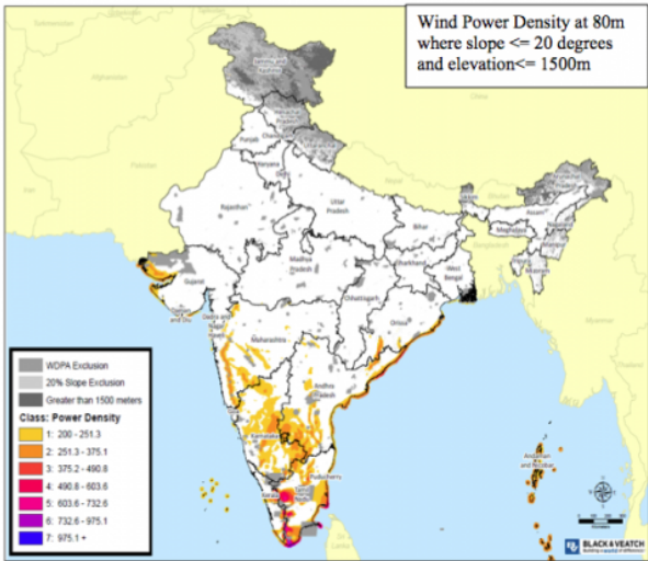
India is known for having a ton of solar energy potential, but a new study from Lawrence Berkeley National Laboratory (LBL) shows that it also has a ton of wind energy potential, much more than previously thought.
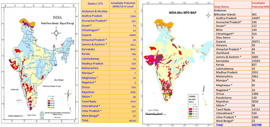
The study found that India has 20-30 times more onshore wind energy potential than the official Indian estimate. This is important, since the official estimate of 102 GW would only be able to provide India with up to 8% of its projected electricity demand by 2022 and 5% by 2032, and since wind is a super-cheap form of energy.
The new Berkeley Lab study has found the total techno-economic wind potential to range from 2,006 GW for 80-meter hub heights (an indication of how high the wind turbine stands above the ground) to 3,121 GW for 120-meter hub heights. More than 95 percent of the wind potential is concentrated in five states in southern and western India.


