Rendering creates a 2D image based on your 3D scene. It shades the scene’s geometry using the lighting you’ve set up, the materials you’ve applied, and environmental settings such as background and fog.

The renderer is a general-purpose renderer that generates physically correct simulations of lighting effects, including ray-traced reflections and refractions, and global illumination. A range of standard rendering presets, reusable rendering parameters, are available. Some of the presets are tailored for relatively quick preview renderings while others are for higher quality renderings.
Face Normals and Hidden Surfaces
In order to minimize the time it takes to render a model, it is common practice to remove hidden surfaces or hide objects that are positioned off camera. Furthermore, ensuring that all face normals orient in the same direction can also speed up the rendering process.
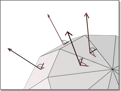
Every surface that you model is made up of faces. Faces are either triangular or quadrilateral and each face has an inward and outward oriented side. The direction in which a face is pointing is defined by a vector called a normal. The direction of the normal indicates the front, or outer surface of the face.
When normals are unified and point in the same outward direction, the renderer processes each face and renders the model. If any normals are flipped, facing inward, the renderer skips them and leaves triangular or quadrilateral “holes” in the rendered image. In instances where you see a hole, it usually means one of two things: Force 2-Sided is turned off in the Render Settings palette or the face is physically missing from the model.
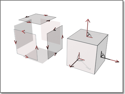
If the face is actually missing, you’ll need to manually reconstruct it. The direction of normals is determined by the way a face is drawn in a right-handed coordinate system: if you draw the face counter-clockwise, the normals point outward; if you draw the face clockwise, the normals point inward. You should draw faces consistently. Solid objects have meshes and normals correctly oriented, which can be an aid to creating models for rendering.
When rendering, the renderer searches for all normals that point away from the viewpoint and removes the associated faces from the scene. This removal step is called back-face culling and is controlled by the Force 2-Sided option on the Render Settings palette.
After the back faces have been removed, the renderer uses a Z buffer to compare relative distances along the Z axis. If the Z buffer indicates that one face overlaps another, the renderer removes the face that would be hidden.
The time saved is in proportion to the number of faces discarded out of the total number of faces.
Sometimes you may want to skip the back-face culling step and leave back faces in (for example, if an object is transparent, if you can see two sides of it because of its shape and orientation, or if an open object will be rendered with a view angle that lets you see inside). Transparency also affects whether one face should hide another. In this situation, make sure Force 2-Sided is active and all faces are rendered no matter which direction their normal is pointing.
If you’re rendering a drawing that wasn’t created with rendering in mind or if the model was created with another product, you should keep Force 2-Sided active. This ensures that all surfaces render correctly. The rendering performance is only marginally affected when Force 2-Sided is active.
Every object in a scene is processed by the renderer, even objects that are “off camera” and are not going to be present in the rendered view. A model that is built with the intent of rendering benefits from good layer management. By turning off layers containing objects that are not in the view, you can optimize rendering speed substantially.
Intersecting Faces
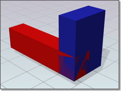
Intersecting faces in a model occur when two objects pass through one other. For conceptual design situations, simply placing one object through another is a fast way to visualize how something will look. However, the edge created where the two objects intersect can exhibit a rippled appearance. In the following example, the edge appears rippled in the left image and much cleaner after a Boolean union.
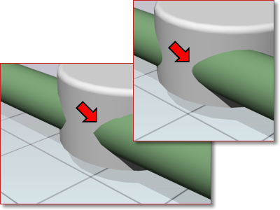
When edges do not appear to be as precise as you want, use Boolean operations like union, intersect, and subtract. A much cleaner and precise edge is created to better reflect the object’s appearance.
Coplanar Faces
Faces that overlap and lie in the same plane, coplanar faces, can produce ambiguous results, especially if the materials applied to the two faces differ. In the following example, artifacts appear when faces occupy the same location.
Moving an object so its faces no longer occupy the same plane as another object will fix this situation.
Twisted Faces
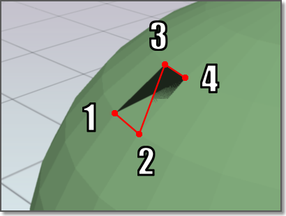
Faces that self-overlap due to a 180-degree twist can also produce ambiguous results, because the normal for the face is not well defined. In the following example, artifacts appear where the face is twisted due to crossing the second and third corner points.
This situation is often encountered when trying to fix a model that has a hole in its surface. For example, when corner points are selected for the new face, the points are crossed instead of being placed around the hole in a counter-clockwise direction. Avoid this problem by choosing corner points in the proper order.
Smooth Geometry
When you render a model, the density of the mesh affects the smoothness of surfaces. Mesh components are comprised of vertices, faces, polygons, and edges.
- A vertex is a point that forms the corner of a face or polygon.
- A face is a triangular portion of a surface object.
- A polygon is a quadrilateral portion of a surface object.
- An edge is the boundary of a face or polygon.
In a drawing, all faces have three vertices, except faces in polyface meshes, which are treated as adjoining triangles. For rendering purposes, each quadrilateral face is a pair of triangular faces that share one edge.
Smoothing of an object is handled automatically by the renderer. Two types of smoothing occur during the rendering process. One smoothing operation interpolates the face normals across a surface. The other operation takes into account the number of faces, the face count, that make up the geometry; greater face counts result in smoother surfaces but longer processing times.
While you cannot control the interpolation of face normals, you can control the display accuracy of curved objects by using the VIEWRES command and the FACETRES system variable.
Set Up the Renderer
You can control many of the settings that affect how the renderer processes a rendering task, especially when rendering higher quality images.
Render Settings Palette
The Render Setting palette contains the main controls for the renderer. You can choose from predefined render settings or make custom settings. The RPREF command opens the Render Settings palette, where you set the parameters for rendering.
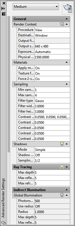
The palette is separated into several sections ranging from basic to advanced settings. The General sections contain settings that affect how your model gets rendered, how materials and shadows are handled, and how anti-aliasing is performed. (Anti-aliasing smooths the stairstep effect at the edge of curved lines or edges.) The Raytracing section controls how shading occurs. The Indirect Illumination section controls lighting properties, how your scene is illuminated, and if global illumination and final gathering are processed. There are also diagnostic controls that can be useful in helping you understand why an image isn’t getting rendered as expected.
Render Presets
A drop-down list provides a collection of predefined render settings called render presets. Render presets store groups of settings that allow the renderer to produce varying quality images. The standard presets range from Draft quality, for quick test images, up to Presentation quality, which provides photorealistic images. You can also open the Render Presets Manager where you can create custom presets.
Create Custom Render Presets
When you specify a collection of render settings that give you the results you want, saving them as a custom preset lets you quickly reuse the settings. Using a standard preset as a base, you can experiment with settings and see how the rendered images look. Once you’re satisfied with the results, you can create a new, custom preset.
You can review and change the render settings for any preset in your drawing in the following ways
- Manage and organize existing render presets.
- Change parameters of standard or existing custom presets.
- Create, update, or delete custom render presets.
- Set a render preset to be used by the renderer.
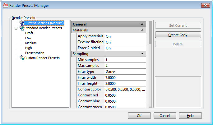
The tree view pane shows all the presets that are stored with the current drawing. The tree view is split between the standard render presets and any custom presets you’ve created. You can change the order of standard and custom presets by dragging one above the other in the tree view. When you create a new preset, it is always added to the Custom Render Presets branch. It will also appear in the Render Presets lists in the Render panel on the ribbon and the Render Settings palette.
Many of the render settings found on the Render Settings palette can also be set in the Render Presets Manager. Using a standard preset as a base, you can make adjustments to the settings and see how the rendered images look. Once you’re satisfied with the results, you can create a new, custom preset. Only custom render presets can be deleted. If you’ve selected a standard preset, the Delete button is inactive.
In order for a render preset to be used by the renderer, it must be made current. While working in the Render Presets Manager, you select presets you want to edit, but in order for the renderer to use them, you have to click the Set Current button. Otherwise, the preset chosen on the Render panel on the ribbon or the Advanced Render Settings palette is used.
If you make changes to a standard render preset, its name is prefaced with an asterisk to indicate that a change has been made to its original settings. If the rendered results are acceptable, you can save the preset by entering a new name in the presets list on the Render panel on the ribbon or on the Render Settings palette.
If you change the settings of a custom render preset, you can enter a new name to create a new, custom render preset or choose to update the preset from the presets list on the Render panel on the ribbon or on the Render Settings palette.
Control the Rendering Environment
You can use environmental features to set up atmospheric effects or background images. You can enhance a rendered image by means of atmospheric effects like fog and depth cueing or by adding a bitmap image as a background.
Fog / Depth Cue Effects – Fog and depth cueing are very similar atmospheric effects that cause objects to appear to fade as they increase in distance from the camera. Fog uses a white color while depth cueing uses black.
The RENDERENVIRONMENT command is used to set up fog or depth cue parameters. The key parameters you’ll set are the color of the fog or depth cueing, the near and far distances, and the near and far fog percentages.
Fog and depth cueing are based on the front or back clipping planes of your camera coupled with the near and far distance settings on the Render Environment dialog box. For example, the back clipping plane of a camera is active and located 30 feet from the camera location. If you want fog to start 15 feet from the camera and spread away indefinitely, you set the Near Distance to 50 and the Far Distance to 100.
The density of the fog or depth cueing is controlled by the Near and Far Fog Percentages. These settings have a range of 0.0001 to 100. Higher values mean the fog or depth cueing is more opaque.
For smaller scale models, the Near and Far Fog Percentage setting may need to be set below 1.0 to see the desired effect.
Backgrounds – A background is basically a backdrop that displays behind your model. Backgrounds can be a single color, a multi-color gradient, or a bitmap image.
Backgrounds work best when you are rendering still images, or animations in which the view doesn’t change or the camera doesn’t move. You set backgrounds from the View Manager. Once set, the background is associated with the named view or camera and is saved with the drawing.
Set the Render Destination
Rendered images appear either in a viewport or get displayed in the Render Window. When you render a scene, the image can be displayed in either the viewport or the Render Window. This is the render destination.
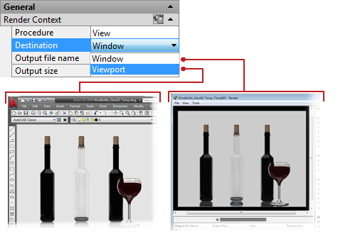
The render destination is set in the Advanced Render Settings palette in the Render Context section. The default setting is Window. When the render destination is set to Window, the renderer automatically opens the Render Window and the image is processed. Upon completion, the image is displayed and a history entry is created. As more renderings occur, they are added to the render history so you can quickly look at previous images and compare to see which have the desired results. Images that you want to keep can be saved from the Render Window.
If you choose to set the render destination to Viewport, the generated image is rendered and displayed directly in the active viewport. In essence, this is a one-time rendering because there is no render history entry that you can compare with later images. If you want to keep the image that you rendered to the viewport, you can use the SAVEIMG command to save the images.
Rendering to a viewport always renders against the background color you set for the drawing area. The Render Window background color matches the background color. Use the REGEN command to refresh the display.
Render a View
The default rendering procedure is to render all objects in the current view in the drawing. If you haven’t opened a named view or a camera view, the current view is rendered. While the rendering process is faster when you render key objects or smaller portions of a view, rendering the entire view lets you see how all objects are oriented to one another.
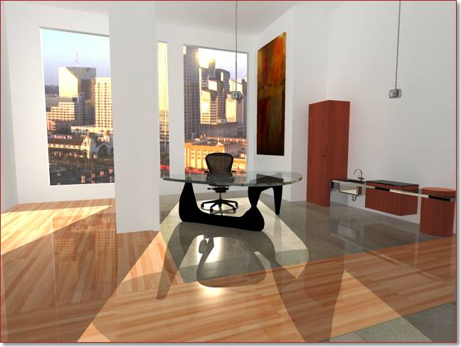
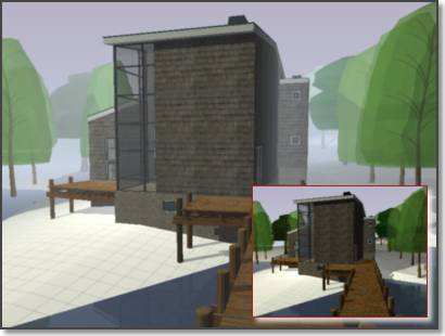
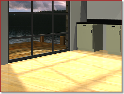
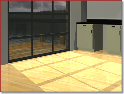
If your current drawing contains named views or if you’ve added cameras to your model, you can quickly display them by using the VIEW command. The following example shows a rendering of a named view.
Depending on the rendering destination you’ve chosen, the rendered view is displayed in the Render Window or directly in the viewport.
Render Selected Objects
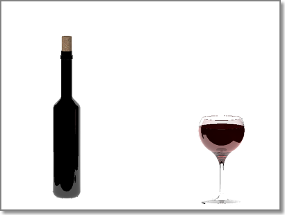
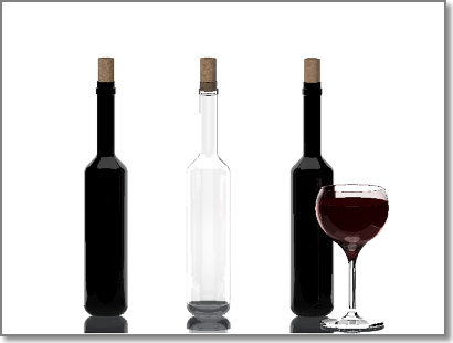
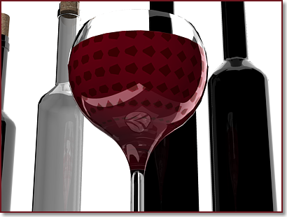
If you’re adding detail to specific objects, you don’t want to waste time rendering an entire viewport. By changing the rendering procedure to Selected, you are prompted to pick the objects that you want rendered. The following example shows a rendered selection of the first bottle, its cork, and the wine glass.
Rendering a selection set of objects is very efficient when testing different materials, especially when the materials include texture mapping. By rendering a selected object, you can quickly verify how the material looks and if its texture coordinates must be altered.
Render a Cropped Region
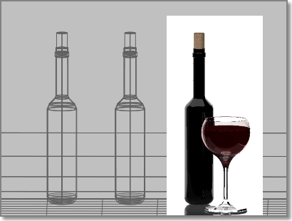
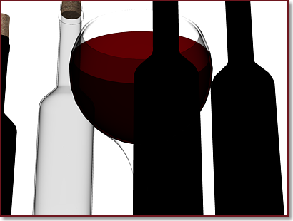
Sometimes you need to render only a portion of what is displayed in the viewport but you still want to see some of the surrounding environment. In the following example, only the region surrounding the third bottle and the wine glass is rendered.
By setting the rendering procedure to Crop, you can specify a smaller region of the viewport to be rendered. Similar to selecting objects by window, you can set a rectangular region in the viewport. Any objects that appear in the region are rendered. Everything outside the region is ignored by the renderer.
Set Output Resolution
Set the resolution of the rendered image by specifying the width and the height of the image, in pixels. There are three resolution settings that control how a rendered image appears; the width, the height, and the image aspect ratio.
The width and height settings control the size of the rendered image, measured in pixels. A pixel (short for Picture Element) is a single point in a graphic image. The default output resolution is 640 x 480 and can be set as high as 4,096 x 4,096. Higher resolution settings result in smaller pixels and finer detail. High resolution images also take longer to render.
Output resolutions are set from the Output Size Dialog Box. You can enter values directly into the width and height fields, or you can use the spinner controls to increase or decrease the resolution.
When you set an output resolution, it gets stored with the current drawing and is added to the output resolution list found in the Render panel of the ribbon. Most often, as you test how objects look in the model, you will find yourself using lower resolution settings, around 320 x 200 or lower. As you add more detail and materials, you’ll shift to mid-range settings, such as 640 x 480. The final rendering will always use the highest resolution required by the project, 1024 x 768 or greater, since this is the image that is presented to the customer or submitted for print.
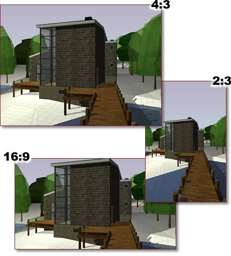
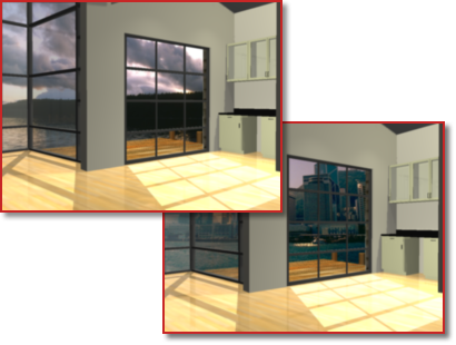
Aspect ratio describes the proportions of a still image or the frames in an animation, expressed as the ratio of width to height, regardless of the image’s resolution. The aspect ratio of an image is controlled by the Image Aspect setting. Aspect ratio is usually expressed either as a ratio of width over height (for example, 4:3) or as a multiplier (such as, 1.333). Changing this value changes the Height value to maintain the correct dimensions for the output resolution. The following example shows various aspect ratios.
If you choose to lock the image aspect, the width and height are tied together; changing one automatically changes the other while maintaining the aspect ratio.
Material Adjustments
Adding materials to objects greatly increases the realism of a model. In the context of rendering, materials describe how an object reflects or transmits light. Within a material, maps can simulate textures, bump effects, reflections, or refractions.
From the Advanced Render Settings palette, you can turn materials on or off, turn material filtering on or off, and affect how the surfaces of an object are rendered. Materials that you’ve created and attached to objects in the model are normally turned on when you start the rendering process. If you turn them off, all the objects in the model assume the characteristics of the GLOBAL material.
Texture Filtering – You can control whether texture filtering, pixel averaging used in anti-aliasing, occurs when the model is rendered.
When texture filtering is turned on, the renderer uses a pyramidal filtering methods, which applies filtering as a function of distance. Irregular anti-aliasing might occur on detailed texture maps that are applied to a surface that recedes into the distance.
There is a slight rendering cost when texture filtering is active. Pyramidal filtering requires memory allocation equal to approximately 133% of the size of a texture map. Compared to the detail and realism provided by texture mapped materials, rendering performance is not impacted that much.
When texture filtering is turned off, no anti-aliasing occurs to texture maps when the renderer processes the model.
2-Sided Rendering – Since you have no control over the direction that faces, normals are pointing, you may encounter a model that has flipped normals. The back sides of faces are invisible to the renderer. This means that the face appears to be missing when viewed from the back. Objects are usually created with the surface normals facing outward, but it is possible to create objects with the faces flipped or to import complex geometry in which the face normals are not properly unified.
When Force 2-Sided is active, both sides of faces are raytraced as shaded. While this incurs a slight increase in rendering time, it is often faster than trying to fix multiple instances of flipped faces.
Shadows in Rendering
With shadows, you can create rendered images that have greater depth and realism. The renderer can generate shadows by shadow mapping or by ray tracing. Shadow mapped shadows rely on a bitmap that the renderer generates during a pre-rendering pass of the scene. Shadow mapping provide softer edges and can require less calculation time than ray-traced shadows, but are less accurate. Ray tracing traces the path of rays sampled from the light source. Shadows appear where rays have been blocked by objects. Ray-traced shadows have more accurate, hard edges and require more calculation time.
Shadow-Mapped Shadows – Shadow maps are the only way to generate soft-edged shadows, but they do not show the color cast by transparent or translucent objects. Shadow-mapped shadows are calculated faster than ray-traced shadows. The following example shows how shadow maps produce softer, less precise shadows that are processed faster than raytraced shadows.
During a pre-rendering pass, a shadow map bitmap is created. Shadow quality can be controlled by increasing or decreasing the size of the shadow map. The default shadow map size is 256 x 256 pixels. If the shadow appears to be too grainy, increasing the map size will give you better quality. Shadow mapped shadows should not be used if you have a light shining through a transparent surface (for example, a multi-pane window where you want the the frame and mullions to cast shadows). You’d have to remove the glass in order for the mullions to cast shadows.
Ray-traced Shadows – Ray-traced shadows (like other ray-traced effects of reflection and refraction) are generated by tracing the path of light beams or rays sampled from a light source. Ray-traced shadows are more accurate than shadow-mapped shadows.
The following example shows that while ray tracing takes longer to process, it produces more realistic, precise shadows.
Ray-traced shadows have hard edges and accurate outlines; they also transmit color from transparent and translucent objects. Therefore, shadows of the frame and mullions of a multi-pane window will render. Because ray-traced shadows are calculated without a map, you don’t have to adjust resolution as you do for shadow-mapped shadows.
Shadow Modes – You can select one of three shadow mode settings when shadows are turned on. The shadow mode can be set to Simple, Sort, or Segment.
The renderer calls shadow shaders in a random order. This is the default mode state for shadows.
- The renderer calls shadow shaders in order, from the object to the light.
- The renderer calls shadow shaders in order along the light ray from the volume shaders to the segments of the light ray between the object and the light.
Displaying Shadows – In order for shadows to be cast in a model, lighting must be established. A light source needs to be added to the scene and you need to specify if that light source will cast shadows. For shadows to display in the viewport as you set up the scene, you need to turn on shadows for the visual style. If you want shadows to appear in the rendered image, you need to turn on shadows and choose the type of shadows to render on the Advanced Render Settings palette.
Ray-traced Reflections and Refractions
Ray tracing traces the path of rays sampled from the light source. Reflections and refractions generated this way are physically accurate. To reduce the time required to generate reflections and refractions, rays are limited by trace depth. Trace depth limits the number of times a ray can be reflected, refracted, or both. You set the maximum trace depth, the maximum number of reflections, and the maximum number of refractions in the Advanced Render Settings palette.
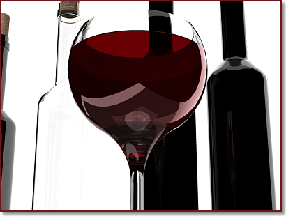
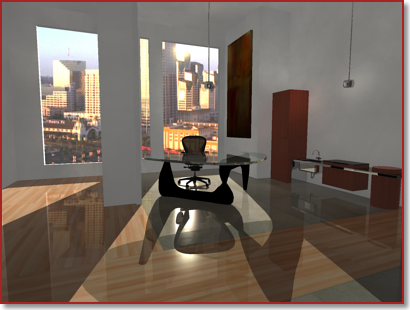
The following example shows how ray-traced reflections and refractions greatly increase the realism of a scene. Max Depth = 8; Max Reflections and Refractions = 4.
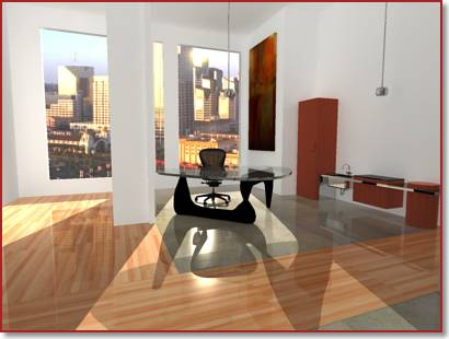
When ray tracing is turned off, no reflection or refraction occurs. The following example shows the same model with ray tracing turned off.
Trace depth controls the number of times a light ray can be reflected or refracted. Increasing these values can increase the complexity and realism of a rendered image, at a cost of greater rendering time. The following example shows how increasing the trace depth improves the rendering. Max Depth = 4; Max Reflections and Refractions = 2.
Ray-tracing Controls – The Max Depth setting limits the combination of reflection and refraction. Tracing of a ray stops when the total number of reflections and refractions reaches the maximum depth. For example, if Max Depth equals 3 and Max Reflections and Max Refractions are both set to 2, a ray can be reflected twice and refracted once, or vice versa, but the ray cannot be reflected and refracted four times.
The Max Reflections setting specifies the number of times a ray can be reflected. At 0, no reflection occurs. At 1, the ray can be reflected once only. At 2, the ray can be reflected twice, and so on. The Max Refractions setting specifies the number of times a ray can be refracted. At 0, no refraction occurs. At 1, the ray can be refracted once only. At 2, the ray can be refracted twice, and so on.
Final Gathering
Final gathering is an optional, additional step used to improve global illumination (GI). It increases the number of rays used to calculate GI to smooth out and eliminate adverse lighting artifacts. Because global illumination is calculated from a photon map, rendering artifacts such as dark corners and low-frequency variations in the lighting may occur.
By activating final gathering, you increase the number of rays used to calculate global illumination, which reduces or eliminates these artifacts.
There is a catch when deciding to use final gathering. Final gathering can greatly increase rendering time. It is most useful for scenes with overall diffuse lighting.
TipLeave final gathering off to preview the scene, then turn it on for the finished rendering. (Increasing the number of photons used to calculate global illumination can also improve global illumination.)
