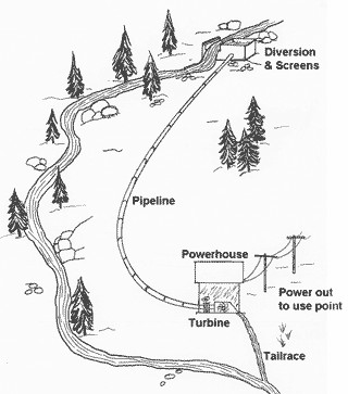
A hydro system is a series of interconnected components: water flows in one end, and electricity comes out the other. This section provides a high-level overview of these components, from the water source to voltage and frequency controls.
Water Diversion (Intake)
The intake is typically the highest point of your hydro system, where water is diverted from the stream into the pipeline that feeds your turbine. In many cases a small dam is used to divert the water. (In most large hydro projects, the dam also creates the HEAD necessary to drive the turbine.)
A water diversion system serves two primary purposes. The first is to provide a deep enough pool of water to create a smooth, air-free inlet to your pipeline. (Air reduces horsepower and can cause damage to your turbine.) The second is to remove dirt and debris. Screens can help stop larger debris such as leaves and limbs, while an area of “quiet water” will allow dirt and other sediment to settle to the bottom before entering your pipeline. This helps reduce abrasive wear on your turbine.
Pipeline (Penstock)
The pipeline, sometimes called the penstock, is responsible for not only moving water to your turbine, but is also the enclosure that creates Head pressure with increasing vertical drop. In effect, the pipeline focuses all the water power at the bottom of the pipe where your turbine will connect. In contrast, an open stream dissipates the energy as it travels down the hill.
Pipeline diameter, length, and routing all affect efficiency, and there are guidelines for matching the size of your pipeline to the Design FLOW of your system. A small-diameter pipeline can considerably reduce available horsepower, even though it can carry all available water. Larger diameter pipelines create less friction as the water travels through.
Powerhouse
The powerhouse is simply a building that houses your turbine, generator and controls. Proper design significantly affects system efficiency, however, especially with regard to how the water enters and exits your turbine.
Turbine
The turbine is the heart of the hydro system, where water power is converted into the rotational force that drives the generator. It is arguably the most important component in the system, because its efficiency determines how much electricity is generated.
There are many different types of turbines, and proper selection requires considerable expertise. A Pelton design, for example, works best with high Head. A Crossflow design works better with low Head but high Flow. Likewise, other turbine types such as Francis, Turgo and Kaplan, each have optimum applications.
Turbines fall into one of two major types:
- Reaction turbines run fully immersed in water, and are typically used in low-Head (pressure) systems with high Flow. Examples include Francis, Propeller and Kaplan.
- Impulse turbines operate in air, driven by one or more high-velocity jets of water. Impulse turbines are typically used with high-Head systems and use nozzles to produce the high-velocity jets. Examples include Pelton and Turgo.
A special case is the Crossflow turbine. Although technically classified as an Impulse turbine because it is not entirely immersed in water, it is used in low-Head, high-Flow systems. The water passes through a large, rectangular opening to drive the turbine blades, in contrast to the small, high-pressure jets used for Pelton and Turgo turbines.
Turbine Efficiency – Regardless of the turbine type, efficiency is in the details. Each turbine type can be designed to meet vastly different requirements, and minor differences in specifications can significantly impact power transfer efficiency.
The turbine system is designed around Net Head and Design Flow. Net Head is the pressure available to the turbine when water is flowing (more on this later), and Design Flow is the maximum amount of Flow the hydro system is designed to accommodate. These criteria not only influence which type of turbine to use, but are critical to the design of the entire turbine system.
Minor differences in specifications can significantly impact power transfer efficiency. The diameter of the runner (the rotating portion), front and back curvatures of its buckets or blades, casting materials, nozzle (if used), turbine housing, and quality of components all have a major affect on efficiency and reliability.
The turbine runs most efficiently when it turns exactly fast enough to consume all the energy of the water. In turn, the water must enter the turbine at a specific velocity (typically measured in feet or meters per second) to maximize efficiency at this RPM. This velocity is determined by Head pressure.
Optimizing Water Velocity – Since power is a combination of HEAD and FLOW, it’s easy to see how a larger orifice that moves more water (Flow) at the same velocity could generate more electricity. Conversely, as Flow drops off in the dry season, the orifice must be made smaller to maintain the same optimum velocity for efficient power transfer.
Keep in mind that turbine speed is not wholly dependent on water velocity; the turbine will turn at a constant speed because it is directly coupled to the generator, where a Governor is maintaining stable RPM by controlling the load. But as the disparity between actual and optimum water velocity grows, less of the energy from the water is transferred to the turbine. The correct orifice ensures the system is operating at its most efficient level.
Impulse turbines (such as a Pelton) are often equipped with a variety of fixed-orifice nozzles that can be used to accommodate changes in Flow. A disadvantage of a fixed nozzle is that the turbine must be shut down to make changes. A popular option is the adjustable needle nozzle, which allows on-the-fly changes with an infinite number of settings.
If you know your Head and Flow, your turbine supplier should be able to make specific recommendations for a turbine system and provide a close estimation of efficiency.
Specific Speed – In practice, modern turbine designs use both reaction and impulse concepts to varying degrees whenever possible. Wind turbines use an airfoil to generate a reaction lift from the moving fluid and impart it to the rotor. Wind turbines also gain some energy from the impulse of the wind, by deflecting it at an angle. Turbines with multiple stages may utilize either reaction or impulse blading at high pressure. Steam turbines were traditionally more impulse but continue to move towards reaction designs similar to those used in gas turbines. At low pressure the operating fluid medium expands in volume for small reductions in pressure. Under these conditions, blading becomes strictly a reaction type design with the base of the blade solely impulse. The reason is due to the effect of the rotation speed for each blade. As the volume increases, the blade height increases, and the base of the blade spins at a slower speed relative to the tip. This change in speed forces a designer to change from impulse at the base, to a high reaction style tip.
Drive System
The drive system couples the turbine to the generator. At one end, it allows the turbine to spin at its optimum RPM. At the other, it drives the generator at the RPM that produces correct voltage and frequency.
The most efficient and reliable drive system is a direct, 1:1 coupling between the turbine and generator. This is possible for many sites, but not for all Head and Flow combinations. In many situations it is necessary to adjust the transfer ratio so that both turbine and generator run at their optimum, but different, speeds.
These types of drive systems can use either gears, or pulley and belts, all of which introduce additional efficiency losses into the system. Belt systems tend to be more popular because of their lower cost. Your turbine manufacturer can provide valuable guidance about matching turbine and generator RPM, and suggest options if a direct, 1:1 coupling is not possible.
Generator
The generator converts the rotational power from the turbine shaft into electrical power. Efficiency is important at this stage too, but most modern, well-built generators deliver good efficiency.
There can be big differences in the type of power generated, however. DC (Direct Current) generators can be used with very small systems, but typically are augmented with batteries and inverters for converting the power into the AC (Alternating Current) power required by most appliances.
AC generators are normally used in all but the smallest systems. Common household units generate 120VAC (volts AC) and 240VAC, which can be used directly for appliances, heaters, lights, etc. AC voltage is also easily changed using transformers, which makes it relatively simple to drive other types of devices or transmit over long distances. Depending on your power requirements, you can choose either single-phase or three-phase AC generators in a variety of voltages.
One critical aspect of AC power is frequency, typically measured as cycles per second (cps) or Hertz (Hz). Most household appliances and motors run on either 50Hz or 60Hz (depending on where you are in the world), as do the major grids that interconnect large power generating stations. Frequency is determined by the rotational speed of the generator shaft; faster rotation generates a higher frequency.
Governors and Controls
Governors and other controls help ensure that the generator constantly spins at its correct speed. The most common types of governors for small hydro systems accomplish this by managing the load on the generator.
To illustrate, consider a hydro system without a governor. When you increase the load on the generator by switching something on, it causes the generator to work harder. Without a governor, it would slow down, lowering both voltage and frequency. Likewise, removing a load by switching something off would cause the generator to speed up, raising voltage and frequency.
With no load whatsoever, the generator would “freewheel,” and run at a very high RPM (possibly causing damage). But by adding progressively higher loads, you would eventually slow the generator until it reached the exact RPM for proper voltage and frequency. As long as you maintain this “perfect” load, known as Design Load, power output will be correct. (Design Load is based on Design Flow. When Flow drops off during dry periods, the load on your generator will need to be reduced as well.)
You might be able to maintain the correct load yourself by manually switching devices on and off, but a governor can do a better job – automatically.
Electronic Load Governors
An electronic load governor works by automatically adjusting the load so the generator always turns at exactly the right speed. In effect, it is always slowing the generator down just enough to produce correct voltage and frequency.
In addition to managing ballast loads, this Load Management Governor can prioritize up to 8 additional devices.
Electronic load governors constantly monitor voltage or frequency, adding or subtracting electrical loads as necessary to compensate for human usage. For example, let’s say our system has a Design Load of 5kW. To maintain proper voltage and frequency, power consumption from the system must always be 5,000 watts. If a person switches off a 1,500 watt stovetop burner, the governor will sense the rising frequency and compensate by switching on a different 1,500 watt load (such as a baseboard heater) to maintain total load at 5kW.
In this example, the governor must have direct control over 5,000 watts of load, so that it can provide total Design Load in the event all human-controlled loads are switched off. Moreover, it must be able to control loads in small increments (perhaps 100 watts) to compensate for light bulbs, small appliances, etc. to keep the frequency exact.
An electronic load governor is highly effective for small systems up to about 12kW. It uses two or more “ballast” loads, which can be any purely resistive device such as a heater. Excess power is shunted to the ballast loads, and a variable electronic switch can regulate the amount of power being directed to the ballast (much as a dimmer switch can regulate power to a light bulb). In this way, the electronic governor can make small-wattage adjustments even though the ballast loads themselves may be quite large.
Load Management Systems
A load management system is an enhanced version of the electronic load governor, offering not only the ability to regulate power usage, but also the option for you to choose and prioritize how power is used. In addition to the ballast loads described above, it can directly control a wide variety of devices via relays.
Small load adjustments work just like the electronic governor; the variable electronic switch regulates power to the ballast loads. When there is enough excess power, however, the load management system will control other devices in a certain priority.
For example, let’s assume you’ve connected two water heaters and a room heater to your load management system. Excess power is directed first to the top priority load, your primary water heater. If there is still excess power available, it will be directed to your next priority, the room heater. If still more power is available, it will go to your backup water heater.
Now assume your well pump kicks on. It draws significant power, but probably runs for less than a minute. Power to one of the water or space heaters may be briefly interrupted while the well pump runs, and then restored when it shuts off. Obviously the brief interruption won’t have a major impact on the availability of hot water or room temperature, and the well pump always has power when it needs it.
Similarly, water in your primary water heater will eventually get hot and the thermostat will switch off. The load management system will automatically compensate, moving down the priority chain until it finds a load it can turn on. Load management systems typically have six or more loads that can be prioritized and switched using relays, and their seamless operation helps facilitate normal household activities, even with relatively small hydro systems.
Emergency System Shutdown
An emergency shutdown system is an option that protects the system from overspeed, which may damage the generator. For example, if a tree falls over a power line, it may cause either a dead short (an extremely high load on the generator) or an open line (zero load) which would cause generator runaway. (A dead short may also cause runaway if it trips a breaker.) Any of these conditions are both dangerous and expensive, so an emergency shutdown system is a wise investment.
Emergency shutdown usually means removing all water power from your turbine. It is important to recognize, however, that an abrupt halt to water flow could damage your pipeline. (If you’ve heard your plumbing “bang” when you’ve turned off a faucet, you get the idea.) For high-flow turbines such as Francis and Crossflow designs, water flow must be reduced gradually.
Emergency shutdown of impulse turbines, such as Pelton and Turgo designs, can be very fast because the water jet can simply be deflected away from the turbine. Since the water flow doesn’t change, there are no damaging surges.
There are many different techniques for managing overspeed conditions, not all of which require an emergency shutdown device. Check with your turbine supplier to see which approach would be appropriate for your hydro system.
Utility Grid Interface Controls
Utility Grid connections are becoming more commonplace, but proper controls are essential for proper operation and – above all – safety.
The grid interconnects very large, public utility power generation systems. It allows hundreds of megawatts of power to move around the country as regional supply and demand change. It provides automatic controls and switchgear, so that a failure in one location can be bypassed with minimal impact to consumers. Most of the time the grid works well, but as illustrated with the widespread U.S. power outage of 2003, it can be remarkably fragile as well.
Electronic Load Management Governor
It is possible to interconnect a small hydro system with the utility grid. Grid connection would allow you to draw power from the grid during peak usage times when your hydro system can’t keep up, and feed excess power back into the grid when your usage is low. If you choose to do so, however, keep in mind that significant synchronization and safeguards must be in place.
Grid interconnection controls do both. They will monitor the grid and ensure your system is generating compatible voltage, frequency, and phase. They will also instantly disconnect from the grid if major fluctuations occur on either end.
Automatic disconnection is critical to the safety of all parties. For example, if a tree falls on a public utility line, their grid controls will automatically shut down that portion of the line. But imagine if your hydro system continued to send power to the downed line. When the public utility line crew shows up to repair what they believe is an inactivated line, they could be in grave danger. You could face the same danger if you were unaware the grid was powering your lines.
If you are thinking about connecting to the utility grid, begin by contacting your utility company to learn their policies. If you expect to sell power back to the utility, pay extra attention to the efficiency of your hydro system, because higher output and a lower cost-per-watt will go straight to your bottom line. Your turbine manufacturer can give you guidance on the most efficient design, as well as grid interconnection controls and safeguards.
