An attribute is a label or tag that attaches data to a block. Examples of data that might be contained in an attribute are part numbers, prices, comments, and owners’ names.
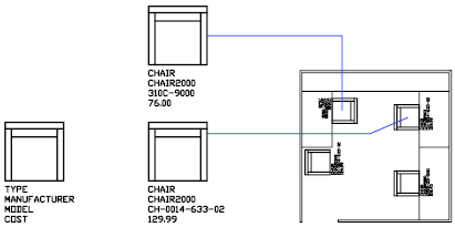
The following illustration shows a “chair” block with four attributes: type, manufacturer, model, and cost. Because the tags were set up as variables, specific information about each instance could be added for each inserted block reference.

Attribute information extracted from a drawing can be used in a spreadsheet or database to produce a parts list or a bill of materials. You can associate more than one attribute with a block, provided that each attribute has a different tag. When you define an attribute, you specify
- A unique tag that identifies the attribute by name
- A prompt that can be displayed as the block is inserted
- A default value that is used if a variable value is not entered at the prompt
If you plan to extract the attribute information for use in a parts list, you might want to keep a list of the attribute tags you create. You will need this tag information later when you create the attribute template file. It is important to make sure that attribute tags have unique names. The Enhanced Attribute Editor will display any duplicate tags in red. Duplicate tags will cause problems when extracting data or if you use them in dynamic blocks.
Attribute Modes
Attribute modes control the behavior of attributes in blocks. For example, you can control
- Whether an attribute is visible or invisible in the drawing. An invisible attribute is not displayed or plotted; however, the attribute information is stored in the drawing file and can be written to an extraction file for use in a database program.
- Whether an attribute is constant or variable. Whenever you insert a block that has a variable attribute, you are prompted to enter data to be stored with the block. Blocks can also use constant attributes whose values do not change. Constant attributes do not prompt you for a value when you insert the block.
- Whether the attribute can be moved relative to the rest of the block. You can use grips to change the position of an attribute without redefining the block. To prevent this movement, you can lock the position of the attribute relative to the other objects in the block.
- Whether the attribute is a single-line attribute or a multiple-line attribute. Unlike single-line attributes (which are limited to 255 characters), multiple-line attributes provide enhanced formatting options.
When a drawing is saved to a legacy AutoCAD-based product (2007 and earlier), a multiple-line attribute is converted to several single-line attributes. If the drawing file is reopened in a later release, the multiple-line attributes are restored.
Attach Attributes to Blocks
After you create one or more attribute definitions, you attach them to a block by including them in the selection set when you define or redefine that block. To use several attributes together, define them and then include them in the same block. For example, you can define attributes tagged “Type,” “Manufacturer,” “Model,” and “Cost,” and then include them in a block called CHAIR.

Usually, the order of the attribute prompts is the same as the order in which you selected the attributes when you created the block. However, if you used crossing or window selection to select the attributes, the order of the prompts is the reverse of the order in which you created attributes. You can use the Block Attribute Manager to change the order in which you are prompted for attribute information when you insert the block reference.
When you open a block definition in the Block Editor, you can use the Attribute Order dialog box (BATTORDER command) to change the order in which you are prompted for attribute information when you insert the block reference.
Stand-alone attributes can also be created. Once attributes have been defined, and the drawing is saved, this drawing file can be inserted into another drawing. When the drawing is inserted, you are prompted for the attribute values.

