Single cell
Besides conducting ions from one electrode to the other, the electrolyte serves as gas separator and electronic insulator. The electrodes are the sites at which the electrochemical reactions take place. Besides containing the suitable catalysts, the electrode architecture should be such that transport of reactants to and products from the catalyst/electrolyte interface is taking place at the maximum possible rate.
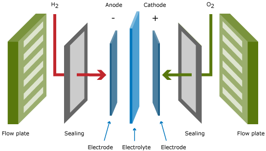
A single fuel cell, as displayed in the Figure above, produces the power, which results from the area times the current density of the cell times the cell voltage. The typical cell voltage under load conditions amounts to 0.6 – 0.7 V, which is too low for practical applications.
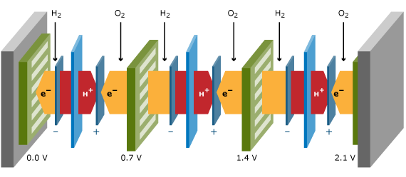
Stacks
It is therefore common practice to put a number of cells in series, resulting in a so-called fuel cell stack. Flow plates connect two adjacent cells. These flow plates, also called separator plates or bipolar plates when a single plate is used for the anode side of one cell and for the cathode side of the other cell, should have a high electronic conductance, and should act as gas separator between the two adjacent cells. The flow plates contain flow patterns on the cell side to generate an even distribution of reactants across the cell area. On the backside, cooling liquid flow patterns transport the heat to a heat exchanger in the system. The stack power and voltage is obtained by the number of cells times the individual cell power and voltage. A three-cell stack is schematically drawn in the Figure below. Besides the repeating units displayed in the Figure above, a stack contains two endplates and two current collector plates from which the current is collected.
Systems
The fuel cell is the core of each fuel cell system, but it does need a number of additional components to make it operate and to let it play its function in its application. The Figure below gives a schematic, simplified display of a typical fuel cell system. The components other than the fuel cell stack and the fuel processor are often called Balance of Plant Components. These Balance of Plant Components are important drivers of system cost, and of system efficiency and durability.
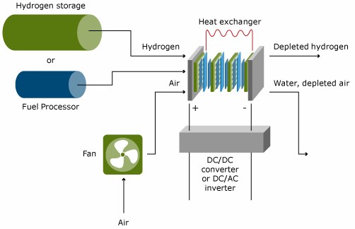
In low temperature fuel cells, except the DMFC, hydrogen is oxidized at the anode to protons. The hydrogen can either be fed from a hydrogen storage container, or produced from another fuel in a so-called fuel processor. Generally, hydrocarbons or alcohols are used as fuels to feed fuel processors. The complexity of the fuel processing depends strongly on the fuel cell type and the primary fuel. In high temperature fuel cells, such as the MCFC and SOFC, fuel processing can be done in the fuel cell itself. This process is referred to as internal reforming.
The air pressure needs to be elevated from ambient pressure up to a level which depends on the operation pressure and the pressure drop in the complete system. This can range from a gauge pressure of 100 mbar to several bars. The power of the fuel cell stack generally increases with increasing pressure; the parasitic loss due to compression however increases as well.
The voltage of the fuel cell stack is the product of the number of cells times the individual cell voltage, which is typically 0.6 – 0.7 V DC. For mobile applications, the voltage should be increased to several hundred Volts and conditioned to the needs of the electric motor. For stationary applications, generally AC voltage is needed, which requires the need for a DC/AC inverter.
