You can create an interactive view of your drawing in the current viewport. Using the 3D viewing and navigation tools, you can navigate through a drawing, set up a camera for a specific view, and create animations to share your design with others.
You can orbit, swivel, walk, and fly around a 3D model, set up a camera, create a preview animation, and record motion path animations that you can distribute to others to visually convey the intent of your design.
3D Navigation Tools
3D navigation tools allow you to view objects in a drawing from different angles, heights, and distances. Use the following 3D tools to orbit, swivel, adjust distance, zoom, and pan in a 3D view.
- 3D Orbit. Moves around a target. The target of the view stays stationary while the camera location, or point of view, moves. The center of the viewport, not the center of the objects you’re viewing, is the target point.
- Constrained Orbit. Constrains 3D Orbit along the XY plane or the Z axis. ( 3DORBIT)
- Free Orbit. Orbits in any direction without reference to the planes. The point of view is not constrained along the XY plane of the Z axis. ( 3DFORBIT)
- Continuous Orbit. Orbits continuously. Click and drag in the direction you want the continuous orbit to move, and then release the mouse button. The orbit continues to move in that direction. ( 3DCORBIT)
- Adjust Distance. Changes the distance of objects as you move the cursor vertically. You can make objects appear larger or smaller, and you can adjust the distance. ( 3DDISTANCE)
- Simulates panning with a camera in the direction that you drag. The target of the view changes. You can swivel the view along the XY plane or along the Z axis. ( 3DSWIVEL)
- Simulates moving the camera closer to an object or farther away. Zooming in magnifies the image. ( 3DZOOM)
- Starts the interactive 3D view and enables you to drag the view horizontally and vertically. ( 3DPAN)
Walk and Fly Through a Drawing
You can simulate walking and flying through a 3D drawing. When you walk through a model, you travel along the XY plane. When you fly through a model, you are not constrained by the XY plane, so you appear to “fly” over an area in a model.
You can use a standard set of keys and mouse interactions to walk and fly through a drawing. Use the four arrow keys or the W, A, S, and D keys to move up, down, left, or right. To toggle between walk and fly mode, press the F key. To specify the direction of the view, drag the mouse in the direction you want to look. Specify walk and fly settings in the 3D Navigate panel on the the ribbon or in the Walk and Fly Settings dialog box. You can set the default step size, the number of steps per second, and other display settings.
DVIEW
You can change a view without interrupting your current operation using a feature that combines panning and zooming.
With dynamic viewing, you can display the effects of changing your viewpoint as you make the changes. Using this method, you can also simplify your view temporarily by choosing only the objects that you need to determine the view. Alternatively, if you press Enter without selecting any objects, 3D Dynamic View displays a model of a small house instead of your actual drawing. You can use this house to define the viewing angle and distance. When your adjustments are complete and you exit the command, the changes are applied to the entire 3D model in the current view.
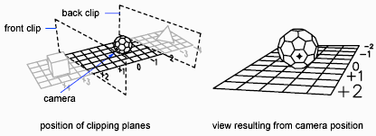
Set Clipping Planes
You can create cutaway, or section, views of your drawing by positioning front and back clipping planes that control the visibility of objects based on their distance from a theoretical camera. You can move the clipping planes perpendicular to the line of sight between the camera and target (where the camera is pointing). Clipping removes the display of objects from the front and back of clipping planes. The following illustration shows how clipping planes work: