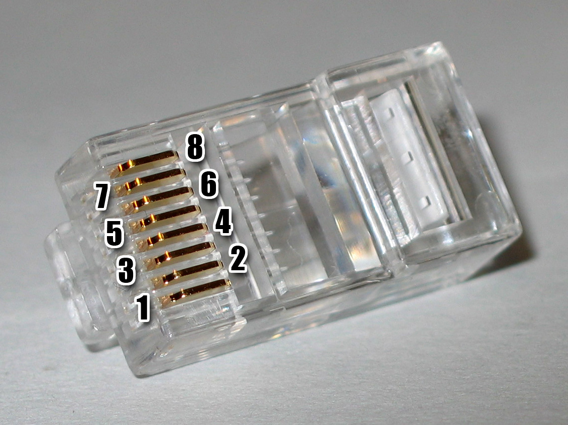
UTP Cabling Pin outs
Wiring
Connectors are frequently terminated using the T568A or T568B pin/pair assignments that are defined in TIA/EIA-568-B. The drawings to the right show that the copper connections and pairing are the same, the only difference is that the orange and green pairs (colors) are swapped. A cable that is wired as T568A at one end and T568B at the other (Tx and Rx pairs reversed) is a "crossover" cable. Before the widespread acceptance of auto-MDI/MDIX capabilities a crossover cable was needed to interconnect similar network equipment (such as hubs to hubs). A cable wired the same at both ends is called a "patch" or "straight-through" cable, because no pin/pair assignments are swapped. Crossover cables are sometimes still used today to connect two computers together without a switch or hub, however most Network Interface Cards (NIC) in use today are called smart, because they automatically configure themselves based on the type of cable plugged into them. If a "patch" or "straight" cable is used to connect two computers with "smart" NICs, the NIC will configure itself to switch the Tx and Rx.
Note that the only difference between T568A and T568B is that pairs 2 and 3 (orange and green) are swapped. Both configurations wire the pins "straight through", i.e., pins 1 through 8 on one end are connected to pins 1 through 8 on the other end. Also, the same sets of pins connect to the opposite ends that are paired in both configurations: pins 1 and 2 form a pair, as do 3 and 6, 4 and 5, and 7 and 8.
| 568A and 568B Pin-out | ||||
|
568A |
568B |
|||
| White/Green | --\ | White/Orange | --\ | Pin 1 |
| Green | --/ | Orange | --/ | Pin 2 |
| White/Orange | ------\ | White/Green | ------\ | Pin 3 |
| Blue | --\ \ | Blue | --\ \ | Pin 4 |
| White/Blue | --/ / | White/Blue | --/ / | Pin 5 |
| Orange | ------/ | Green | ------/ | Pin 6 |
| White/Brown | --\ | White/Brown | --\ | Pin 7 |
| Brown | --/ | Brown | --/ | Pin 8 |
Even you are using Cat 5 cable with 4 twisted pair wires, it doesn't mean that the cable is 100% compliant with EIA/TIA standard if it is not connected to RJ-45 in the way it should be. The Straight-through cable ("Patch cable") connection should be:
Pin 1 and 2 are connected to same twisted pair wire
Pin 3 and 6 are connected to same twisted pair wire
Pin 4 and 5 are connected to same twisted pair wire
Pin 7 and 8 are connected to same twisted pair wire
Here is the pin-out for Crossover cable ("Uplink cable"):
Point A Point B
TR+ Pin 1 ----- Pin 3 RCV+
TR- Pin 2 ----- Pin 6 RCV-
RCV+ Pin 3 ----- Pin 1 TR+
RCV- Pin 6 ----- Pin 2 TR-


